1
Locomotion
1.1 Introduction
An
Autonomous Mobile Robotics (AMR)
needs locomotion mechanisms which enable it to move
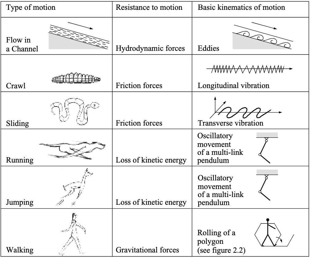
Most locomotion mechanisms have been inspired by biological counterparts, shown in Fig. 1.1 .
There is, however, one
Actively powered wheel is a human invention achieving high efficiency on flat ground.
This
mechanism
is
NOT
completely
foreign
to
biological
systems
Biological systems succeed in moving through a wide variety of harsh environments. Therefore it
can be desirable to copy their selection of locomotion mechanisms
-
Mechanical complexity is easily achieved in biological systems through structural replication.
Cell division, in combination with specialisation, can readily produce a millipede with several hundred legs and several tens of thousands of individually sensed cilia
3 3 short eyelash-like filament that is numerous on tissue cells of most animals and provides the means for locomotion of protozoans of thephylum Ciliophora . In man-made structures, each part must be fabricated individually, and therefore, no such economies of scale exist. -
Cell is a microscopic building block that enables extreme miniaturisation. With very small size and weight, insects achieve a level of robustness that we have not been able to match with human fabrication techniques.
-
The biological energy storage system and the muscular and hydraulic activation systems used in animals and insects achieve torque, response time and conversion efficiencies that far exceed similarly scaled man-made systems.
Based on these aforementioned limitations, mobile robots generally generate motion, either using wheeled mechanisms, a well-known human technology for vehicles, or using a small number of articulated legs, the simplest of the biological approaches to locomotion (shown in Fig. 1.2 ).
In general, legged locomotion requires higher Degrees of Freedom (DoF) and therefore greater mechanical complexity than wheeled locomotion [5]. Wheels, in addition to being simple, are extremely well suited to flat ground. As Fig. 1.3 depicts, on flat surfaces wheeled locomotion is one to two orders of magnitude more efficient than legged locomotion.
The railway is ideally engineered for wheeled locomotion because rolling friction is minimised using a hard and flat steel surface.

But as the surface becomes soft, wheeled locomotion accumulates inefficiencies due to rolling friction while legged locomotion suffers much less because it consists only of point contacts with the ground. This is demonstrated in figure 2.3 by the dramatic loss of efficiency in the case of a tire on soft ground.
the efficiency of wheeled locomotion depends on environmental qualities, such as the flatness and hardness of the ground, while the efficiency of legged locomotion depends on the leg mass and body mass, both of which the robot must support at various points in a legged gait.
It is understandable therefore nature favours legged locomotion, as locomotion systems in nature must operate on rough and unstructured terrain. For example, in the case of insects in a forest the vertical variation in ground height is often an order of magnitude greater than the total height of the insect.
By the same token, the human environment frequently consists of engineered, smooth surfaces both indoors and outdoors. Therefore, it is also understandable that virtually all industrial applications of mobile robotics utilise some form of wheeled locomotion. Recently, for more natural outdoor environments, there has been some progress toward hybrid and legged industrial robots such as the forestry robot [6] shown in Fig. 1.4 .
In the next section, we present general considerations that concern all forms of mobile robot locomotion. Following this will be overviews of legged locomotion and wheeled locomotion techniques for mobile robots.
1.1.1 Key Issues for Locomotion
Locomotion is the
-
In manipulation, the robot arm is fixed but moves objects in the workspace by imparting force to them.
-
In locomotion, the environment is fixed and the robot moves by imparting force to the environment.
For both cases, the scientific basis is the
-
Stability
-
number and geometry of contact points
-
centre of gravity
-
static/dynamic stability
-
inclination of terrain
-
-
characteristics of contact
-
contact point/path size and shape
-
angle of contact
-
friction
-
-
type of environment
-
structure
-
medium (e.g., water, air, soft or hard ground)
-
A theoretical analysis of locomotion begins with mechanics and physics. From this starting point, we can formally define and analyse all manner of mobile robot locomotion systems. However, this Lecture Book puts more emphasis on the mobile robot navigation problem, particularly on the topics of perception, localisation and cognition. Therefore, we will not delve deeply into the physical basis of locomotion. Nevertheless, two remaining sections in this chapter present overviews of issues in legged locomotion and wheeled locomotion.
1.2 Legged Mobile Robots
Legged locomotion is characterised by a
The dung beetle, is capable of rolling a ball while locomotion as a result of its dexterous front legs shown in Fig. 1.5 .
The main disadvantages of legged locomotion include
Leg Configurations and Stability
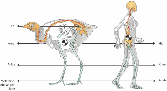
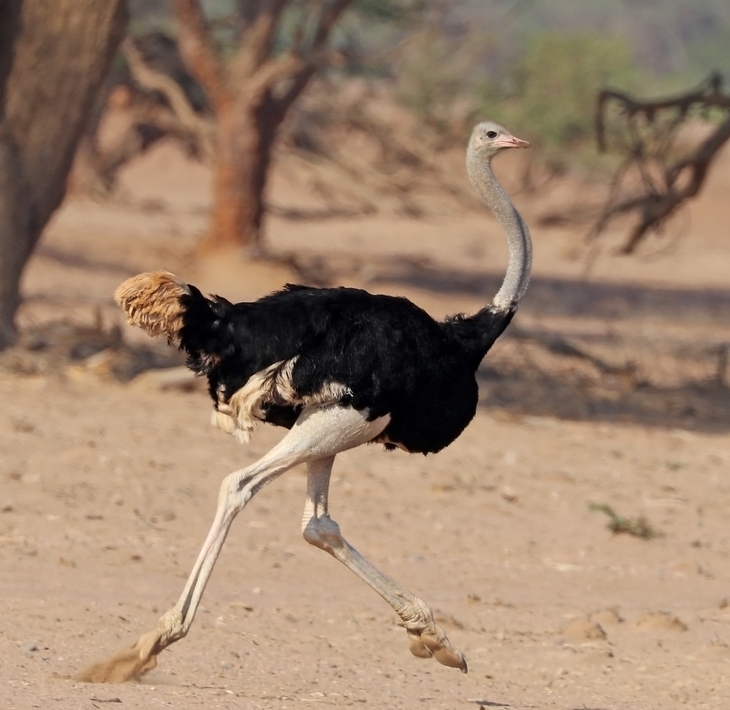
Because legged robots are biologically inspired, it is instructive to examine biologically successful legged systems. A number of different leg configurations have been successful in a variety or organisms seen in Fig. 1.6 .
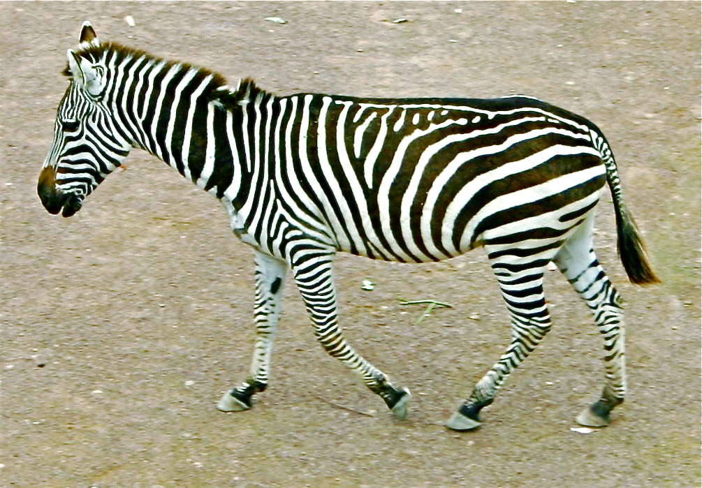

Large
animals
such
as
mammals
and
reptiles
have
four
Bipedal motion is much more complex active control to maintain balance.
In
contrast,
a
creature
with
three
Insects
There is also the potential for great variety in the complexity of each individual leg. Once again, the biological world provides ample examples at both extremes. For instance, in the case of the caterpillar, each leg is extended using hydraulic pressure by constricting the body cavity and forcing an increase in pressure, and each leg is retracted longitudinally by relaxing the hydraulic pressure, then activating a single tensile muscle that pulls the leg in towards the body, seen in Fig. 1.7 . Each leg has only a single DoF , which is oriented longitudinally along the leg. Forward locomotion depends on the hydraulic pressure in the body, which extends the distance between pairs of legs. The caterpillar leg is therefore mechanically very simple, using a minimal number of extrinsic muscles to achieve complex overall locomotion.
At
the
other
extreme,
the
human
leg
has
more
than
six
In
the
case
of
legged
mobile
robots,
a
minimum
of
two
In the case of a multi-legged mobile robot, there is the issue of leg coordination for locomotion, or gait control.
The number of possible gaits depends on the number of legs [21].
The gait is a sequence of lift and release events for the individual legs. For a mobile robot with legs, the total number of possible events for a walking machine is:
|
|
(1.1) |
For a bipedal walker ( =2) legs the number of possible events is:
|
|
(1.2) |
The
six
-
lift right leg
-
lift left leg
-
release right leg
-
release left leg
-
lift both legs together
-
release both legs together
As
can
we
see,
this
list
of
possible
events
quickly
grows
quite
large.
For
example,
a
robot
with
six
|
|
(1.3) |
1.2.1 Examples of Legged Robot Locomotion
Although there are no high-volume industrial applications to date, legged locomotion is an important area of long-term research. Several interesting designs are presented below, beginning with the one-legged robot and finishing with six-legged robots.
Single Leg
The minimum number of legs a legged robot can have is, of course, one. Minimising the number of legs is beneficial for several reasons.
-
Body mass is particularly important to walking machines, and the single leg minimises cumulative leg mass.
-
Leg coordination is required when a robot has several legs, but with one leg no such coordination is needed.
-
The one-legged robot maximises the basic advantage of legged locomotion: legs have single points of contact with the ground in lieu of an entire track as with wheels.
A single legged robot requires only a sequence of single contacts, making it useful in rough terrain.
Perhaps most importantly, a hopping robot can dynamically cross a gap that is larger than its stride by taking a running start, whereas a multi-legged walking robot that cannot run is limited to crossing gaps that are as large as its reach.
The
major
challenge
of
creating
a
single-leg
robot
is
Fig. 1.10 shows the Raibert Hopper [ 23 , 24 ], one of the most well-known single-leg hopping robots created.
This robot makes continuous corrections to body attitude and to robot velocity by adjusting the leg angle with respect to the body. The actuation is hydraulic, including high-power longitudinal extension of the leg during stance to hop back into the air. Although powerful, these actuators require a large, off-board hydraulic pump to be connected to the robot at all times. Fig. 1.11 shows a more energy efficient design developed [26]. Instead of supplying power by means of an off-board hydraulic pump, the Bow Leg Hopper is designed to capture the kinetic energy of the robot as it lands using an efficient bow spring leg. This spring returns approximately 85% of the energy, meaning that stable hopping requires only the addition of 15% of the required energy on each hop. This robot, which is constrained along one axis by a boom, has demonstrated continuous hopping for 20 minutes using a single set of batteries carried on board the robot. As with the Raibert Hopper, the Bow Leg Hopper controls velocity by changing the angle of the leg to the body at the hip joint. The paper of Ringrose [27] demonstrates the very important duality of mechanics and controls as applied to a single leg hopping machine. Often clever mechanical design can perform the same operations as complex active control circuitry. In this robot, the physical shape of the foot is exactly the right curve so that when the robot lands without being perfectly vertical, the proper corrective force is provided from the impact, making the robot vertical by the next landing. This robot is dynamically stable, and is furthermore passive.
The correction is provided by physical interactions between the robot and its environment, with no computer nor any active control in the loop.
Two Legs (Bipedal)
A variety of successful bipedal robots have been demonstrated. Two-legged robots have been shown to run, jump, travel up and down stairs and even do aerial tricks such as somersaults. Fig. 1.12 shows the Honda P2 bipedal robot, which is the product of tens of millions of research dollars and more than a decade of work. This biped can walk on slopes, climb and descend stairs, and push shopping carts. The crucial technology that enables this robot is Honda’s research into the fabrication of extremely high torque, low mass motors that serve as the robot’s joints. In the case of P2, the most significant obstacle that remains is energy capacity, efficiency and autonomous navigation. This robot can operate for only about 20 minutes with on-board power. An important feature of bipedal robots is their anthropomorphic shape. They can be built to have the same approximate dimensions as humans, and this makes them excellent vehicles for research in human-robot interaction.
Bipedal robots can only be statically stable within some limits, and so robots such as P2 and Wabian generally must perform continuous balance-correcting servoing even when standing still. Furthermore, each leg must have sufficient capacity to support the full weight of the robot. In the case of four-legged robots, the balance problem is facilitated along with the load requirements of each leg. An elegant design of a biped robot is the Spring Flamingo of MIT seen in Fig. 1.13 . This robot inserts springs in series with the leg actuators to achieve a more elastic gait. Combined with "kneecaps" that limit knee joint angles, the Flamingo achieves surprisingly biomimetic motion.
Four Legs (Quadruped)
Although standing still on four legs is passively stable, walking remains challenging because to remain stable the robot’s center of gravity must be actively shifted during the gait. Sony recently invested several million dollars to develop a four-legged robot (figure 2.14). To cre- ate this robot, Sony created both a new robot operating system that is near real-time and invented new geared servomotors that are sufficiently high torque to support the robot, yet backdriveable for safety. In addition to developing custom motors and software, Sony incorporated a color vision system that enables Aibo to chase a brightly colored ball. The robot is able to function for at most one hour before requiring recharging. Early sales of the robot have been very strong, with more than 60,000 units sold in the first year. Nevertheless, the number of motors and the technology investment behind this robot dog have resulted in a very high price of approximately 1500. Four legged robots have the potential to serve as effective artifacts for research in human- robot interaction (fig. 2.15). Humans can treat the Sony robot, for example, as a pet and might develop an emotional relationship similar to that between man and dog. Furthermore, Sony has designed Aibo’s walking style and general behavior to emulate learning and maturation, resulting in dynamic behavior over time that is more interesting for the owner who can track the changing behavior. As the challenges of high energy storage and motor technology are solved, it is likely that quadruped robots much more capable than Aibo will become common throughout the human environment.
Six Legs (Hexapod)
Six legged configurations have been extremely popular in mobile robotics because of their static stability during walking, thus reducing the control complexity (figure 2.16 and 2.17). In most cases, each leg has 3 DOF, including hip flexion, knee flexion and hip abduction (figure 2.6).
Genghis is a commercially available hobby robot that has six legs, each of which has 2 DOF provided by hobby servos (figure 2.18). Such a robot, which consists only of hip flexion and hip abduction, has less maneuverability in rough terrain but performs quite well on flat ground. Because it consists of a straightforward arrangement of servo motors and straight legs, such robots can be readily built by a robot hobbyist. Insects, which are arguably the most successful locomoting creatures on earth, excel at traversing all forms of terrain with six legs, even upside down. Currently, the gap between the capabilities of six-legged insects and artificial six-legged robots is still quite large. Interestingly, this is not due to a lack of sufficient numbers of degrees of freedom on the robots. Rather, insects combine a small number of active degrees of freedom with passive structures, such as microscopic barbs and textured pads, that increase the gripping strength of each leg significantly. Robotic research into such passive tip structures has only recently begun. For example, a research group is attempting to recreate the complete mechanical function of the cockroach leg (Roland, reference in notes (Espenschied et al.)). It is clear from all of the above examples that legged robots have much progress to make before they are competitive with thei24 Autonomous Mobile Robots have been realised recently, primarily due to advances in motor design. Creating actuation systems that approach the efficiency of animal muscle remains far from the reach of robotics, as does energy storage with the energy densities found in organic life forms
1.3 Wheeled Mobile Robots
The
wheel
has
been
by
far
the
most
popular
locomotion
mechanism
in
mobile
robotics
and
in
man-made
vehicles
in
general.
Therefore,
can the robot wheels provide sufficient traction and stability for the robot to cover all of the desired terrain, and does the robot’s wheeled configuration enable sufficient control over the velocity of the robot?
1.3.1 Design
As we will see, there is a very large space of possible wheel configurations when we considers possible techniques for mobile robot locomotion. We will begin by discussing the wheel in detail, as there are a number of different wheel types with specific strengths and weaknesses. Then, we will examine complete wheel configurations that deliver particular forms of locomotion for a mobile robot.
Wheel Design
There
are
four
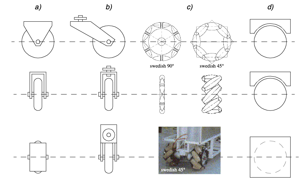
The
standard
wheel
and
the
castor
wheel
have
a
The
mecanum
wheel
The spherical wheel is a truly omnidirectional wheel, often designed so that it may be actively powered to spin along any direction. One mechanism for implementing this spherical design imitates the computer mouse, providing actively powered rollers that rest against the top surface of the sphere and impart rotational force.
Regardless
of
what
wheel
is
used,
in
robots
designed
for
all-terrain
environments
and
in
robots
with
more
than
three
Wheel Geometry
The choice of wheel types for a mobile robot is strongly linked to the choice of wheel arrangement, or wheel geometry.
When designing a mobile robot locomotion we must consider these two
-
maneuverability,
-
controllability
-
stability.
Unlike
automobiles,
which
are
largely
designed
for
a
highly
standardised
environment
the paved road.
However, there is no single wheel configuration that maximises these qualities for the variety of environments faced by different mobile robots. So, we will see great variety in the wheel configurations of mobile robots. In fact, few robots use the Ackerman wheel configuration of the automobile because of its poor maneuverability, with the exception of mobile robots designed for the road system (figure 2.20).
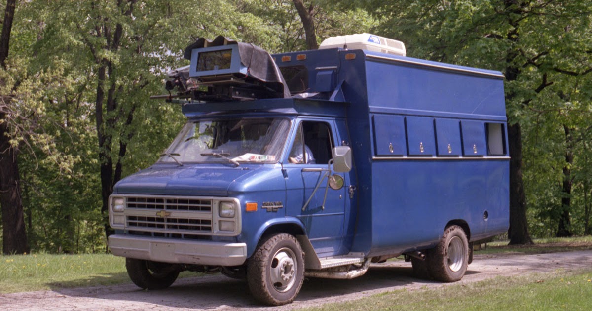
Table 2.1 gives an overview of wheel configurations ordered by the number of wheels. This table shows both the selection of particular wheel types and their geometric configuration on the robot chassis. Note that some of the configurations shown are of little use in mobile robot applications. For instance, the 2-wheeled bicycle arrangement has moderate maneu- verability and poor controllability. Like a single-leg hopping machine, it can never stand still. Nevertheless, this table provides an indication of the large variety of wheel configura- tions that are possible in mobile robot design.
1.3.2 Stability
Surprisingly,
the
minimum
number
of
wheels
required
for
static
stability
is
two
However,
under
ordinary
circumstances
such
a
solution
requires
wheel
diameters
that
are
impractically
large.
Dynamics
can
also
cause
a
two-wheeled
robot
to
strike
the
floor
with
a
third
point
of
contact,
for
instance
with
sufficiently
high
motor
torques
from
standstill.
Conventionally,
static
stability
requires
a
minimum
of
three
1.3.3 Manoeuvrability
Some robots are omnidirectional, meaning that they can move at any time in any direction along the ground plane regardless of the orientation of the robot around its vertical axis. This level of maneuverability requires wheels that can move in more than just a single direction, and so omnidirectional robots usually employ swedish or spherical wheels that are powered. A good example is Uranus, shown in figure 2.24. This robot uses four swedish wheels to rotate and translate independently and without constraints. In general, the ground clearance of robots with swedish and spherical wheels is somewhat limited, due to the mechanical constraints of constructing omnidirectional wheels. An inter- esting recent solution to the problem of omnidirectional navigation while solving this ground clearance problem is the four castor-wheeled configuration in which each castor wheel is actively steered and actively translated. In this configuration, the robot is truly om- nidirectional because, even if the castor wheels are facing a direction perpendicular to the desired direction of travel, the robot can still move in the desired direction by steering these wheels. Because the vertical axis is offset from the ground contact path, the result of this steering motion is robot motion.
In the research community, another classes of mobile robots are popular which achieve high maneuverability, only slightly inferior to that of the omnidirectional configurations. In such robots, motion in a particular direction may initially require a rotational motion. With a cir- cular chassis and an axis of rotation at the center of the robot, such a robot can spin without changing its ground footprint. The most popular such robot is the two-wheel differential drive robot where the two wheels rotate around the center point of the robot. One or two ad- ditional ground contact points may be used for stability, based on the application specifics.
In contrast to the above configurations, consider the Ackerman steering configuration com- mon in automobiles. Such a vehicle typically has a turning diameter that is larger than the car. Furthermore, for such a vehicle to move sideways requires a parking maneuver consist- ing of repeated changes in direction forward and backward. Nevertheless, Ackerman steer- ing geometries have been especially popular in the hobby robotics market, where a robot can be built by starting with a remote-control race car kit and adding sensing and autonomy to the existing mechanism. In addition, the limited maneuverability of Ackerman steering has an important advantage: its directionality and steering geometry provide it with very good lateral stability in high speed turns.
1.3.4 Controllability
There
is
generally
an
Controlling an omnidirectional robot for a specific direction of travel is also more difficult and often less accurate when compared to less manoeuvrable designs.
For example, an Ackerman steering vehicle can go straight simply by locking the steerable wheels and driving the drive wheels, which can be seen in Fig. 1.18 .
In
a
differential
drive
vehicle,
the
two
In summary, there is NO “ideal” drive configuration that simultaneously maximises stability, manoeuvrability and controllability. Each mobile robot application places unique constraints on the robot design problem, and the designer’s task is to choose the most appropriate drive configuration possible from among this space of compromises.
1.3.5 Case Studies for Wheeled Motion
Now
let’s
describe
four
Synchro Drive
The synchro drive configuration (figure 2.22) is a popular arrangement of wheels in indoor mobile robot applications. It is an interesting configuration because, although there are three driven and steered wheels, only two motors are used in total. The one translation motor sets the speed of all three wheels together, and the one steering motor spins all the wheels together about each of their individual vertical steering axes. But note that the wheels are being steered with respect to the robot chassis, and therefore there is no direct way of re-orienting the robot chassis. In fact, the chassis orientation does drift over time due to uneven tire slippage, causing rotational dead-reckoning error.
Synchro drive is particularly advantageous in cases where omnidirectionality is needed. So long as each vertical steering axis is aligned with the contact path of each tire, the robot can always re-orient its wheels and move along a new trajectory without changing its footprint. Of course, if the robot chassis has directionality and the designers intend to re-orient the chassis purposefully, then synchro drive is only appropriate when combined with an independently rotating turret that attaches to the wheel chassis. Commercial research robots such as the Nomadics 150 or the RWI B21r have been sold with this configuration (figure 1.12). In terms of dead-reckoning, synchro drive systems are generally superior to true omni-directional configurations but inferior to differential drive and Ackerman steering systems. There are two main reasons for this. First and foremost, the translation motor generally drives the three wheels using a single belt. Due to slop and backlash in the drivetrain, whenever the drive motor engages, the closest wheel begins spinning before the furthest wheel, causing a small change in the orientation of the chassis. With additional changes in motor speed, these small angular shifts accumulate to create a large error in orientation during dead-reckoning. Second, the mobile robot has no direct control over the orientation of the chassis. Depending on the orientation of the chassis, the wheel thrust can be highly asymmetric, with two wheels on one side and the third wheel alone, or symmetric, with one wheel on each side and one wheel straight ahead or behind, as shown in (2.22). The asymmetric cases results in a variety of errors when tire-ground slippage can occur, again causing errors in dead-reckoning of robot orientation.
Omnidirectional Drive
As we will see later in chapter 3.4.2, omnidirectional movement is be of great interest for complete maneuverability. Omnidirectional robots that are able to move in any direction ( ) at any time are also holonomic (see chapter 3.4.2). They can be realized by either using spheric, castor or swedish wheels. Three examples of such holonomic robots are pre- sented below.
Omnidirectional locomotion with three spheric wheels
The omnidirectional robot depicted in figure 2.23 is based on three spheric wheels, each ac- tuated by one motor. In this design, the spheric wheels are suspended by three contact points, two given by spherical bearings and one by the a wheel connected to the motor axle. This concept provides excellent maneuverability and is simple in design. However, it is limited to flat surfaces and small loads, and it is quite difficult to find round wheels with high fric- tion coefficients
Omnidirectional locomotion with four swedish wheels
The omnidirectional arrangement depicted in figure 2.24 has been used successfully on sev- eral research robots, including the CMU Uranus. This configuration consists of four swedish 45 degree wheels, each driven by a separate motor. By varying the direction of rotation and relative speeds of the four wheels, the robot can be moved along any trajectory in the plane
and, even more impressively, can simultaneously spin around its vertical axis. For example, when all four wheels spin "forward" or "backward", the robot as a whole moves in a straight line forward and backward, respectively. However, when one diagonal pair of wheels is spun in the same direction and the other diagonal pair is spun in the opposite direction, the robot moves laterally. This four-wheel arrangement of swedish wheels is not minimal in terms of control motors. Because there are only 3 degrees of freedom in the plane, one can build a three-wheeled om- nidirectional robot chassis using three swedish 90 degree wheels as shown in Table 2.1. However, existing examples such as Uranus have been designed with four wheels due to ca- pacity and stability considerations. One application for which such omnidirectional designs are particular amenable is mobile manipulation. In this case, it is desirable to reduce the degrees of freedom of the manipulator arm to save arm mass by using the mobile robot chassis motion for gross motion. As with humans, it would be ideal if the base could move omnidirectionally without greatly impact-
Omnidirectional locomotion with four castor wheels and eight motors
Another solution for omnidirectionality is to use castor wheels. This is done for the Nomad XR4000 form Nomadics (fig. 2.25) giving it an excellent maneuverability. Unfortunately Nomadics Technology has ceased the production of mobile robots. The above two examples are drawn from Table 2.1, but this is not an exhaustive list of all wheeled locomotion techniques. Hybrid approaches that combine legged and wheeled loco- motion, or tracked and wheeled locomotion, can also offer particular advantages. Below are two unique designs created for specialized applications.
Tracked Slip/Skid Locomotion
In the wheel configurations discussed above, we have made the assumption that wheels are not allowed to skid against the surface. An alternative form of steering, termed slip/skid, may be used to re-orient the robot by spinning wheels that are facing the same direction at different speeds or in opposite directions. The army tank operates this way, and Nanokhod, pictured below (figure 2.26) is an example of a mobile robot based on the same concept. Robots that make use of tread have much larger ground contact patches, and this can signif- icantly improve their maneuverability in loose terrain compared to conventional wheeled designs. However, due to this large ground contact patch, changing the orientation of the ro- bot usually requires a skidding turn, wherein a large portion of the track must slide against the terrain. The disadvantage of such configurations is coupled to the slip/skid steering. Because of the large amount of skidding during a turn, the exact center of rotation of the robot is hard to predict and the exact change in position and orientation is also subject to variations depend- ing on the ground friction. Therefore, dead-reckoning on such robots is highly inaccurate. This is the trade-off that is made in return for extremely good maneuverability and traction over rough and loose terrain. Furthermore, a slip/skid approach on a high-friction surface can quickly overcome the torque capabilities of the motors being used. In terms of power efficiency, this approach is reasonably efficient on loose terrain but extremely inefficient otherwise.
1.3.6 Walking Wheels
Walking robots might offer the best maneuverability in rough terrain. However, they are in- efficient on flat ground and need sophisticated control. Hybrid solutions, combining the adaptability of legs with the efficiency of wheels offer an interesting compromise. Solutions that passively adapt to the terrain are of particular interest for field and space robotics. The Sojourner robot of NASA/JPL (fig. 1.2) represents such a hybrid solution, able to overcome objects up to the size of the wheels. A more advanced mobile robot design for similar appli- cations has recently been produced by EPFL (fig. 2.27). This robot, called Shrimp2, has 6 motorized wheels and is capable of climbing objects up to two times its wheel diameter [84,85]. This enables it to climb regular stairs though the robot is even smaller than the So- journer. Using a rhombus configuration, the Shrimp has a steering wheel in the front and the rear, and two wheels arranged on a bogy on each side. The front wheel has a spring suspen- sion to guarantee optimal ground contact of all wheels at any time. The steering of the rover is realized by synchronizing the steering of the front and rear wheels and the speed differ- ence of the bogy wheels. This allows for high precision maneuvers and turning on the spot with minimum slip/skid of the four center wheels. The use of parallel articulations for the front wheel and the bogies creates a virtual center of rotation at the level of the wheel axis. This ensures maximum stability and climbing abilities even for very low friction coeffi- cients between the wheel and the ground. As mobile robotics research matures we find ourselves able to design more intricate me- chanical systems. At the same time, the control problems of inverse kinematics and dynam2 Locomotion 37 R. Siegwart, EPFL, Illah Nourbakhsh, CMU ics are now so readily conquered that these complex mechanics can in general be controlled. So, in the near future, you should expect to see a great number of unique, hybrid mobile ro- bots that draw together advantages from several of the underlying locomotion mechanisms that we have discussed in this chapter. They will each be technologically impressive, and each will be designed as the expert robot for its particular environmental niche.