Appendix C
Photographs of the Experimental Setups
C.1 Experimental Setup
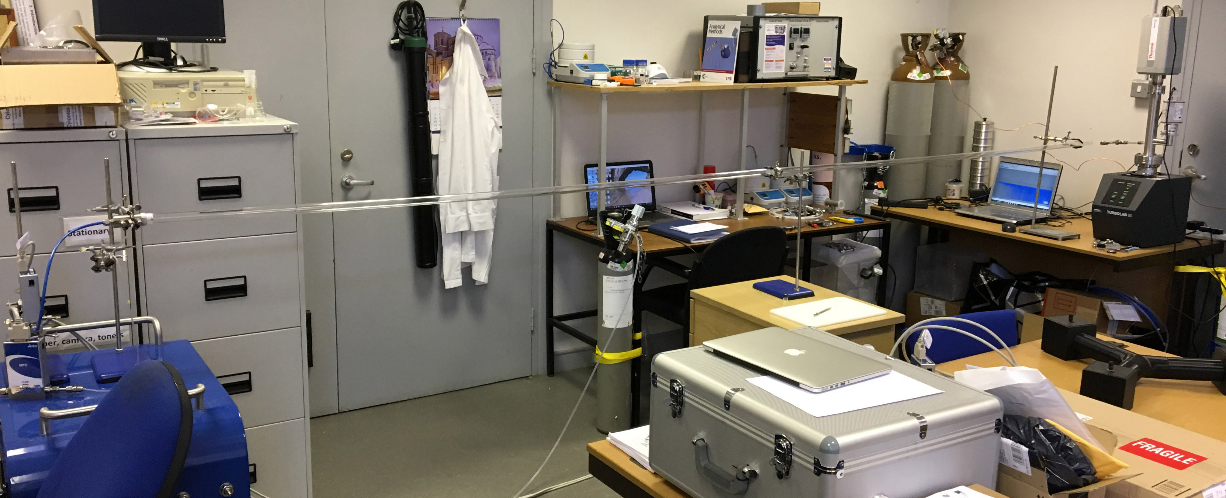
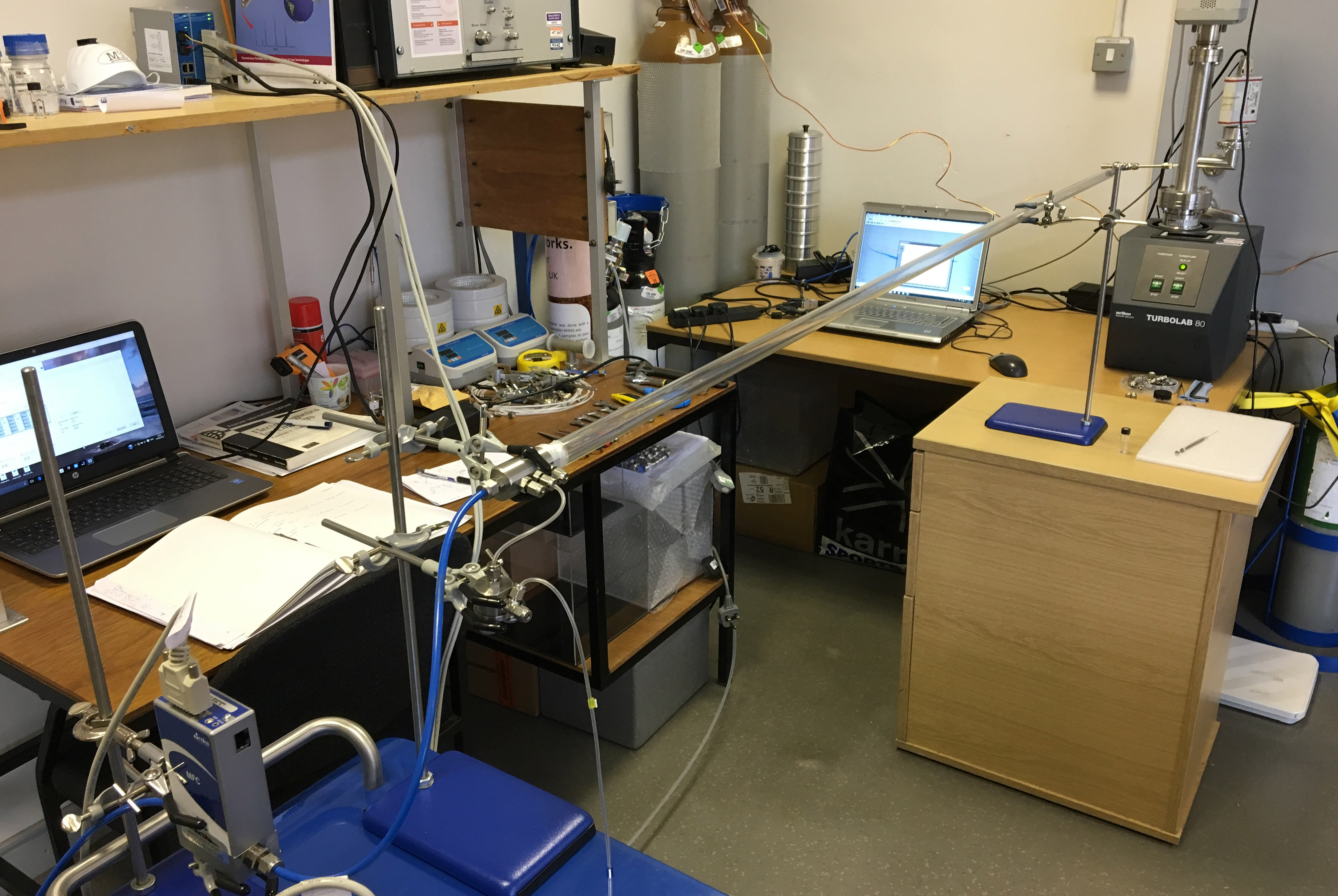
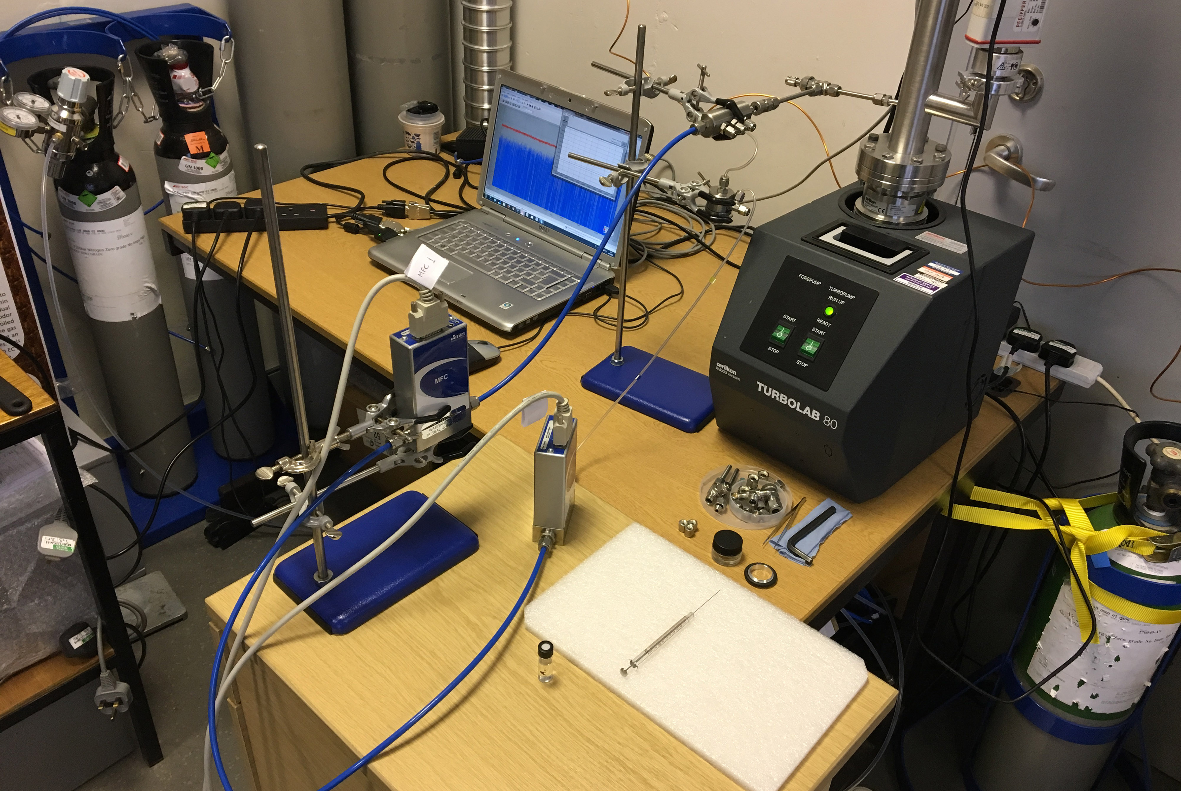
Figure C.1: (A), (B)Experimental setup for long distance transmission. (C) Experimental
setup for short distance transmission.
C.2 Transmitter
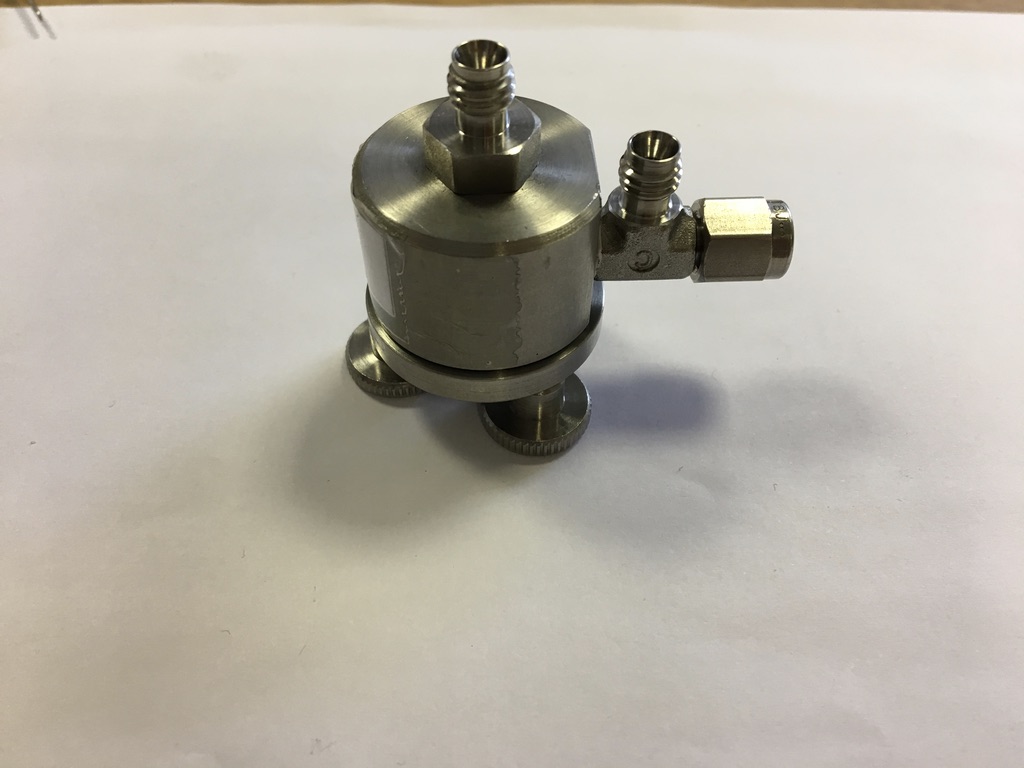
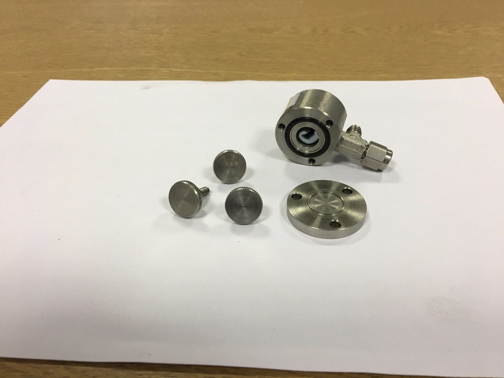
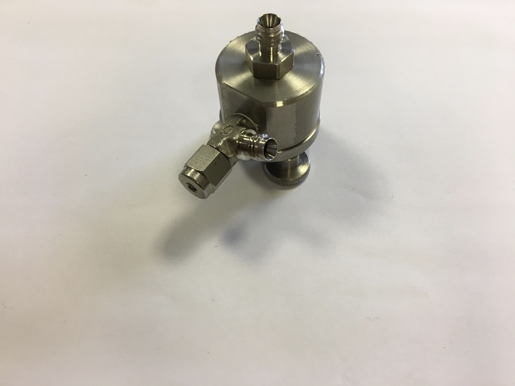
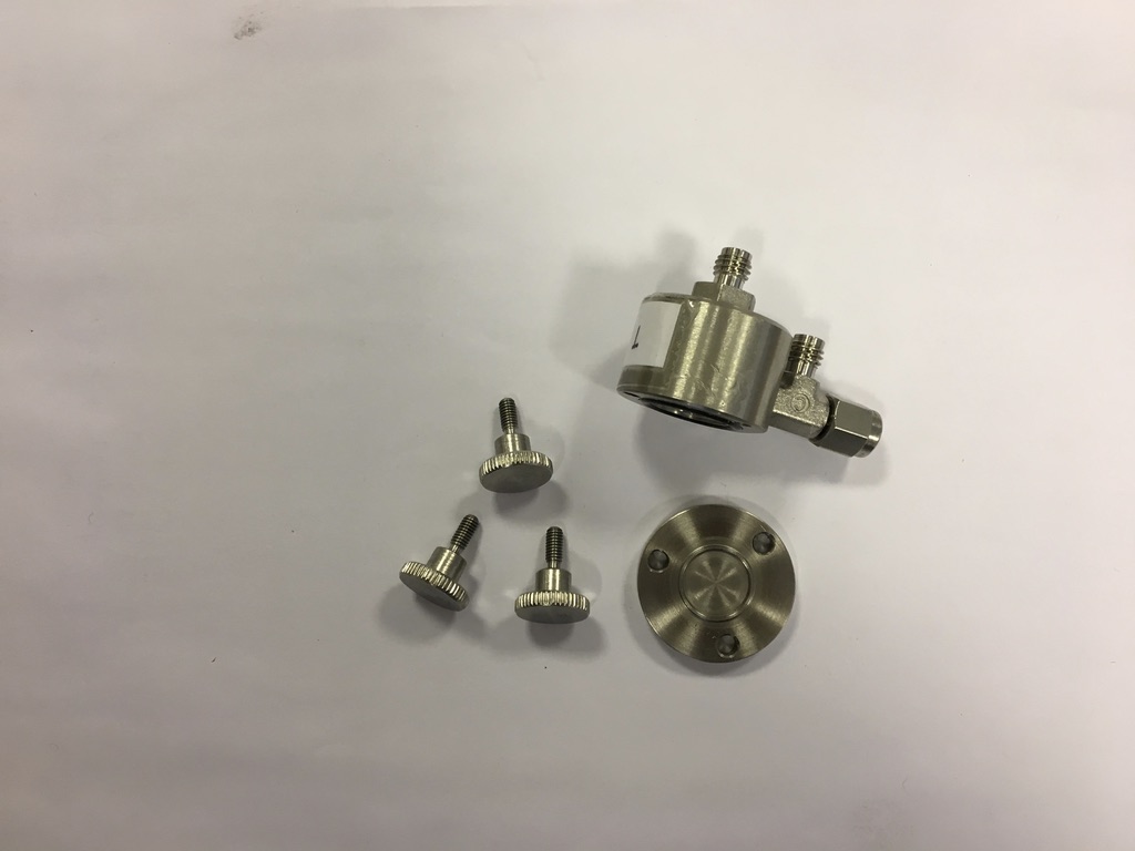
C.2.1 Odour Generator
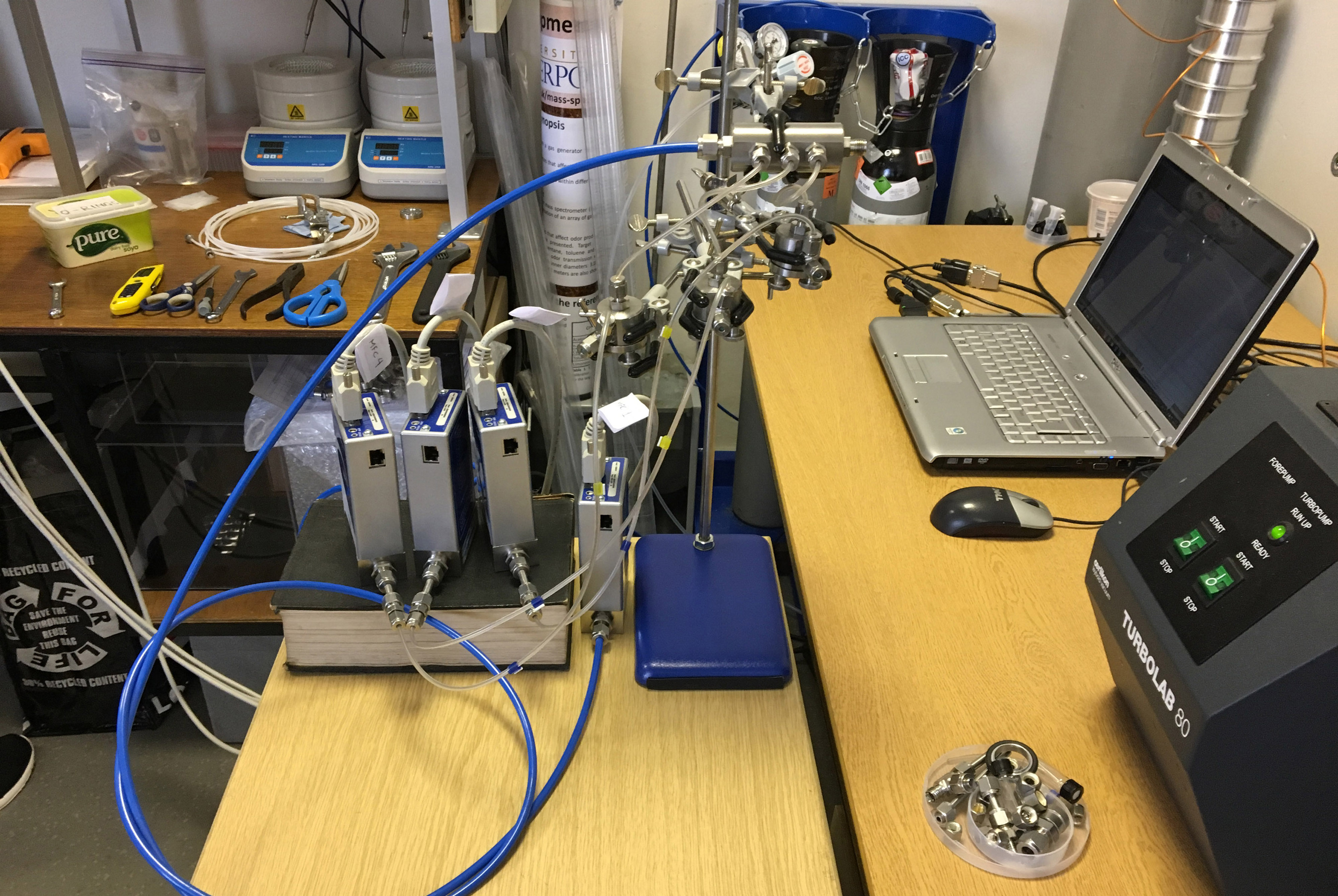
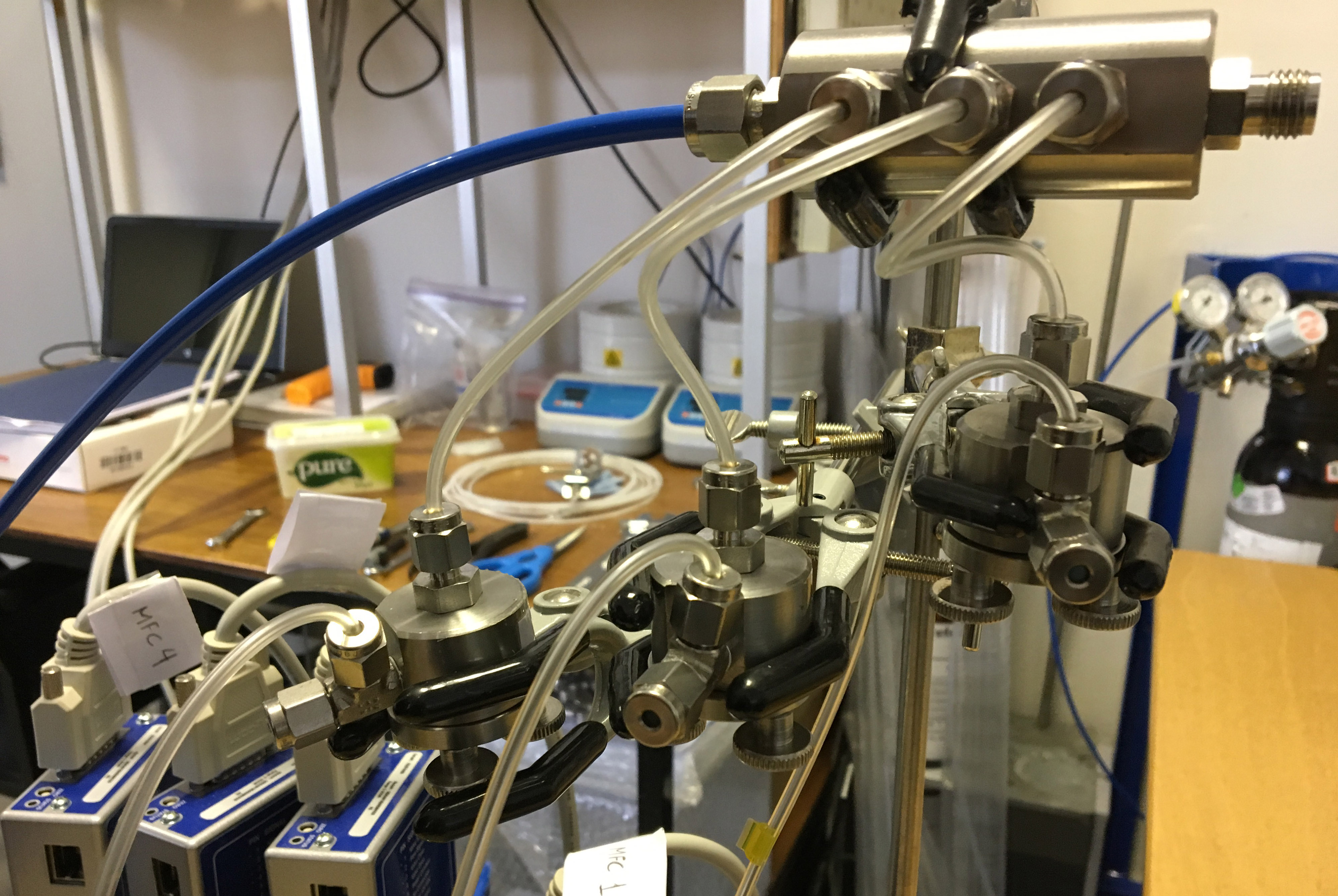
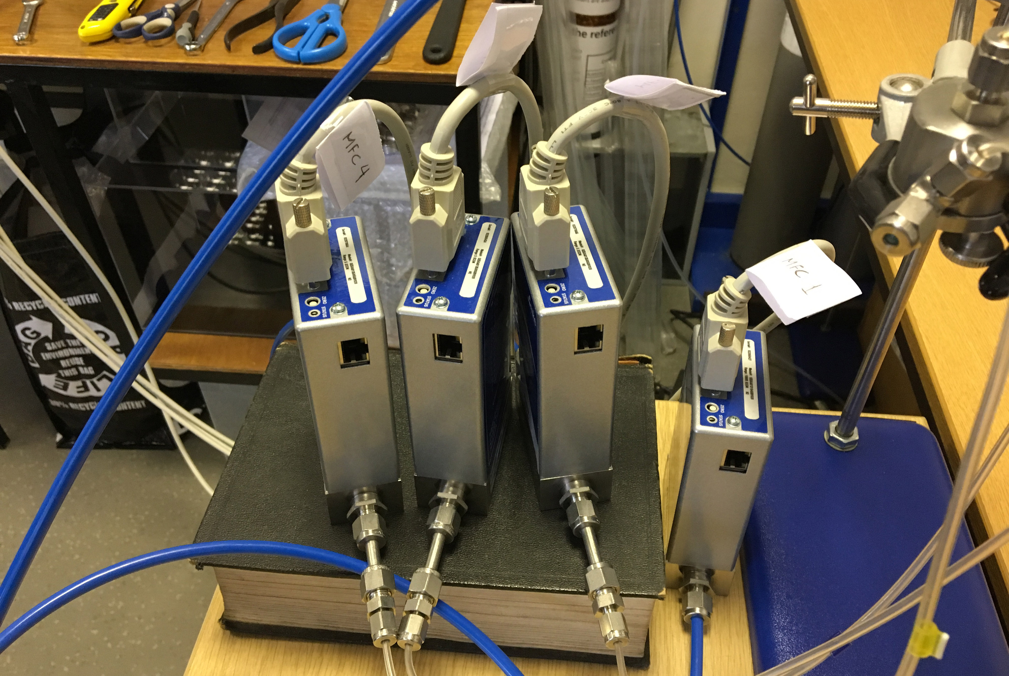
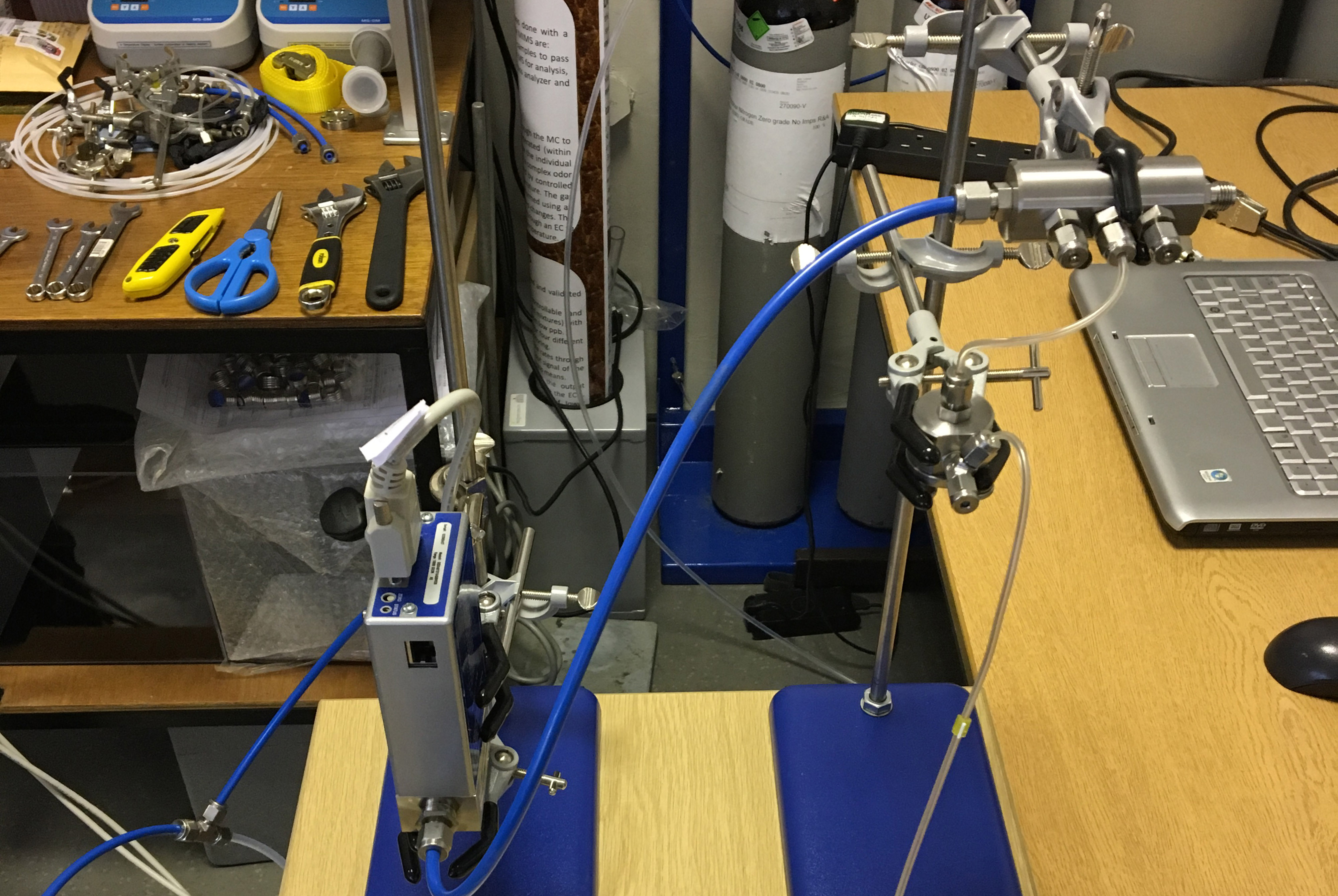
Figure C.2: (A) The odour generator with three evaporation chambers and mass flow
controllers attached. (B) A close-up of the evaporation chambers connected to the odour
generator. (C) A close-up of the mass flow controllers connected to evaporation chambers. (D)
An odour generator with a single evaporation chamber and mass flow controller attached.